A workbench should do more than hold whatever pile of tools you have not put away yet. I wanted a solid assembly surface, useful storage, an integrated router table, power where I actually needed it, and dust collection that did not require dragging a vacuum around the shop.
Apparently, I also wanted a project with enough opportunities to screw up that I could demonstrate most of them personally.
This is my Versatile Workbench, built around a laminated lumber frame with customizable plywood inserts. It has leveling casters, a hardwood-trimmed MDF top, T-track, organizer storage, drawers, and a router lift with a custom fence. It remains one of my favorite pieces of shop furniture, but getting there was not exactly a flawless operation.
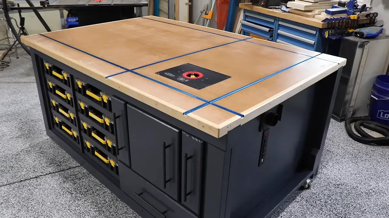
What You'll Learn
- A laminated frame and separate storage inserts make a complex workbench easier to build and customize.
- Install drawer slides, electrical components, and dust hoses before surrounding cabinetry restricts access.
- Keep fasteners clear of planned routing paths and use sacrificial backers to prevent edge blowout.
- A collecting router fence and under-table enclosure dramatically reduced visible dust during routing tests.
Table of Contents
- Start With a Frame, Then Build Around It
- Build the Laminated Lumber Base
- Choose Casters for Stability, Not Just Mobility
- Make a Stiff, Hardwood-Edged Workbench Top
- Build the Storage as Separate Inserts
- Install the Router Lift and Collection Box
- Keep the Workbench Electrical System Plug-and-Play
- Fit Compact Dust Collection Inside the Bench
- Build the Drawers and Router-Bit Pullouts
- Seal the MDF and Install the T-Track
- Add Face Frames, Doors, and Drawer Fronts
- Prep, Paint, and Reassemble
- Install an Accessible Router Switch
- Build a Custom Router-Table Fence
- What Actually Made This Workbench Worth Building
Start With a Frame, Then Build Around It
For large shop furniture, I like building a sturdy frame first and adding the other components to it. That separates the main structure from the storage layout. Instead of building one enormous cabinet that has to come together all at once, I can work on individual inserts and customize them around what I need.
The main features of this build are:
- A laminated 2x4 frame with lap-jointed corners and internal stretchers.
- A layered work surface made from 3/4-inch MDF and 1/2-inch plywood.
- Separate storage inserts for organizer bins, conventional drawers, and router accessories.
- Integrated utilities with plug-in electrical components and compact dust collection.
- A built-in router table with a lift, enclosed collection box, external switch, and adjustable fence.
The modular approach gives you flexibility, but it does not mean assembly order is irrelevant. Some tasks are dramatically easier before a cabinet is assembled or an opening disappears behind another component. I managed to prove that repeatedly.
The full workbench plans include the detailed measurements, cut sheets, and assembly information, with a metric version available too.
Build the Laminated Lumber Base
Cut the parts long and laminate them
I started by batching out the lumber with a stop block at the miter saw. When several parts need matching lengths, a stop block saves a lot of measuring and makes consistency much easier.
The pieces were intentionally left long. A small reference mark helped align the laminations, but perfect end alignment was not important yet because I would trim everything to final length after the glue dried.
Rather than finding 2,000 clamps and making the obligatory clamp joke, I distributed screws along the laminations to hold the layers together during the glue-up. I left those screws installed afterward.
Keep track of every embedded fastener before any later machining. Screws are convenient clamps right up until a cutting tool finds one.
Mill the laminations to their final size
After the glue cured, I cleaned up the rounded edges of the 2x4s and brought the members to a final width of 3.25 inches. I used a little 6-inch benchtop jointer, taking 1/16-inch cuts and making two passes per side.
It worked for this application, and the dust collection was surprisingly good. Supporting pieces roughly six feet long on a small tabletop jointer, however, was easily one of the sketchiest parts of the frame build. That is not a setup I would recommend copying casually. Use an appropriate, supported milling setup rather than treating my successful outcome as proof that the approach was ideal.
Once the edges were cleaned up, I trimmed the frame members to their exact lengths.
Square the lap-jointed frames before locking them together
The laminated pieces form lap joints at the corners. I initially drove one screw at each corner, just enough to hold the assembly together while I adjusted it square. Then I added the remaining fasteners, bringing each joint to five screws.
That sequence matters: hold the shape first, establish square, then lock it in. Driving every screw before checking the diagonals just makes a crooked frame more committed to being crooked.
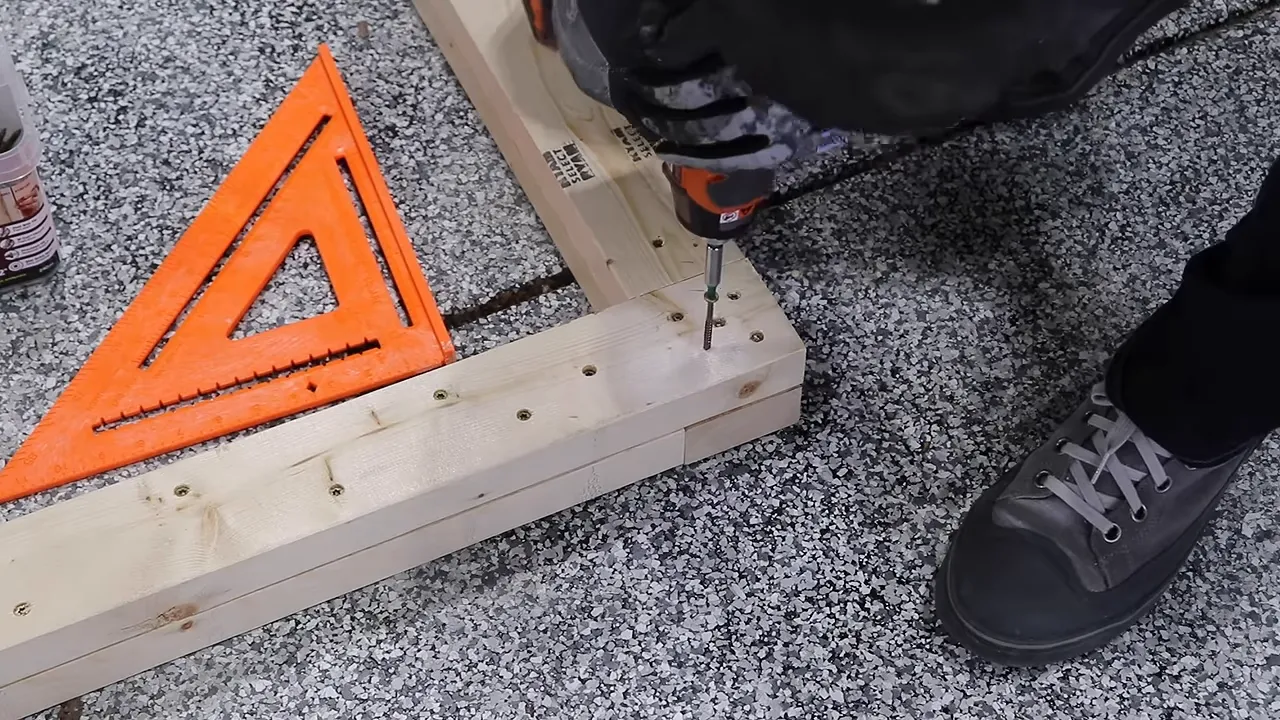
I oriented the joints so one complete side had no visible screw heads. It is shop furniture, but there is nothing wrong with making it look intentional.
The stretchers and braces were prepared next, with most connections using pocket-hole screws. Their height was also brought to 3.25 inches. Before joining the main frames, I cleaned up the lap-joint surfaces so high spots would not interfere with the worktop sitting flat.
A couple of 48-inch clamps made assembly much easier. Pocket screws have a habit of shifting parts as they tighten, so clamping the members in position before driving screws is worth the effort.
Choose Casters for Stability, Not Just Mobility
This bench uses heavy-duty leveling casters with retractable feet. Turning the adjustment wheel lowers a foot and lifts the caster wheel off the floor.
The set I used was rated for a combined 2,200 pounds. I am pretty sure the workbench would have problems before the casters did, but that rating belongs to the caster set, not to the completed wooden structure.
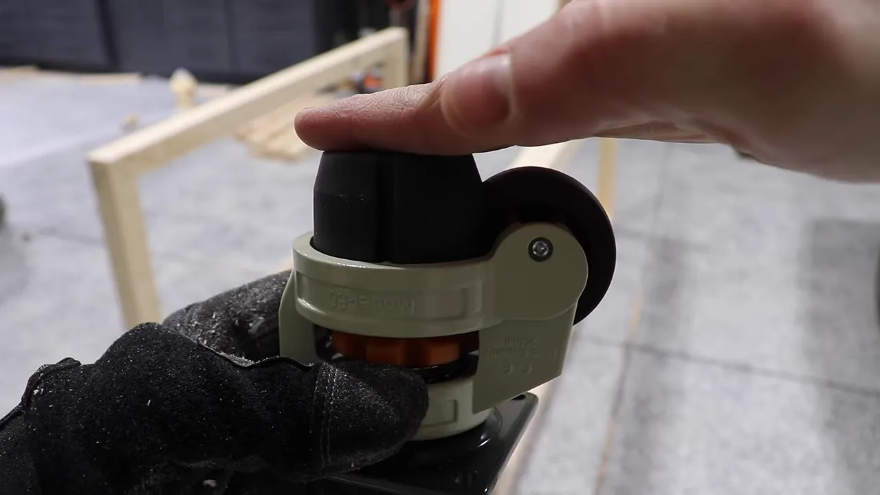
The mounting arrangement deserves a little explanation:
- The casters are not supported by two pocket screws. Glued and screwed caster blocks reinforce each corner.
- The end panels contribute to the structure. They tie the lower stretchers into the upper stretchers.
- The inset mounting preserves interior height. Mounting directly beneath the main frame would be stronger, but it would sacrifice vertical space inside the bench.
There is a tradeoff. Adjusting these feet takes more effort than stepping on a locking caster. I do not plan to move this bench constantly, so I am happy to trade quick adjustment for the stability of having it sit on feet.
Make a Stiff, Hardwood-Edged Workbench Top
Laminate MDF to plywood
The top consists of 3/4-inch MDF bonded to 1/2-inch plywood. The MDF provides the work surface, while the plywood adds stiffness and leaves supporting material beneath the channels that will eventually hold the T-track.
I spread glue between the sheets and used wide pan-head screws as temporary clamps. Screw length is important here for the fairly obvious reason that a screw sticking through your new work surface is not an upgrade.
Unlike the screws in the frame laminations, these screws all came out after the glue cured.
My top needed about 48 hours before I returned to it. Cold Midwestern weather in an unheated garage did not exactly encourage speedy glue curing. Do not treat that as a universal cure time. Follow the adhesive’s temperature and curing requirements for your conditions.
Hide the top fasteners
On previous benches, I simply countersunk screws through the top. That is perfectly fine, and it is the easier option.
For this build, I wanted concealed fasteners, so I recessed figure-eight brackets into the frame and screwed upward into the underside of the work surface. The brackets need to sit flush so they do not hold the top above the frame.
These brackets are not lifting points. Do not grab the top and try to pick up the entire workbench. This attachment method is suitable for how I use the bench, not for hoisting all that weight by the work surface.
Add hardwood trim and plan around future cuts
I wrapped the exposed MDF and plywood edges in maple. Hardwood trim hides the layers and protects the perimeter from the inevitable bumps that happen around a shop.
Miters are optional. Butt joints work just fine. I chose miters because apparently I cannot leave well enough alone.
The brad nails did not cooperate with the hard maple, so I removed what I could, predrilled, and used finish screws instead. Before installing either nails or screws, mark the planned T-track locations and keep metal out of those paths.
I did give myself that advice. Whether I successfully followed it is another matter.
The edging also extended slightly below the worktop. My attempt to flush-trim it ended when the router bit’s bearing broke off halfway through. Rather than continue around the entire perimeter, I notched the underside of the edging only where it needed to clear the frame.
With the top attached, I cleaned up the surface, sanded it, and added a small chamfer around the upper edge.
Build the Storage as Separate Inserts
The storage modules use 1/2-inch and 3/4-inch plywood. Early in the project, I broke down parts with a Kreg track saw and the Adaptive Cutting System on my compact workbench because I did not yet have my table saw available.
Later, with the table saw in place, I still used the track saw for breaking down full sheets. That hybrid approach worked really well: reduce the sheet to manageable pieces first, then finish the parts at the table saw.
Install drawer slides before assembling the boxes
If there is one cabinet-building shortcut worth remembering, it is this: lay out and install the drawer slides while the side panels are still flat.
It is much easier than reaching into a narrow assembled cabinet. Mark the top and bottom edges of every panel, too. Those reference marks help prevent mirrored parts and upside-down assemblies.
They do not eliminate mistakes completely. I initially positioned a center divider so its drawer slides did not line up correctly. Fortunately, I had only installed one screw and the glue had not set.
Use the backs to add rigidity and establish square
My assembly method was consistent across the inserts:
- Apply glue and use brad nails to hold the parts in rough alignment.
- Check the assembly and add clamps where useful.
- Predrill and reinforce the joints with countersunk screws.
- Fit the back panel while checking the cabinet for square.
A little clamp pressure across a diagonal was enough to persuade the organizer cabinet into square before securing its back. The back panel adds a lot of rigidity, so it is worth getting the shape right at that stage.
The organizer insert supports sliding trays for removable parts organizers. That gives me access to the containers without digging through a stack.
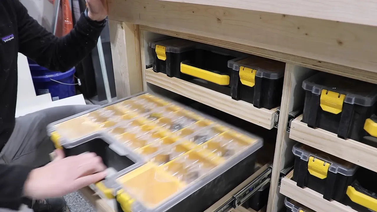
I also built a separate four-drawer insert and a router-table storage insert. Another test-fit revealed that I had installed a vertical frame support in the wrong location. The cabinet was not the problem. My ability to follow my own plans was.
Test-fit the inserts, but leave them accessible until the electrical components and dust hoses are installed. There is very little extra room inside this design.
Install the Router Lift and Collection Box
Fit the lift to its own mounting requirements
Cutting a big opening in a freshly finished-looking top is always a special kind of stressful.
I used a Kreg Precision Router Lift, which I considered a good balance of price and capability for this build. Whatever lift you choose, follow that manufacturer’s mounting instructions. The opening and supporting recess need to match the actual hardware, not an approximation based on another lift.
With the lift installed, I built a collection box beneath it to enclose the router area.
Make the box accessible
The box has a removable front door held by small magnets and a flange around the top for mounting beneath the work surface.
Check magnet polarity before gluing them in. Then apparently check it again, because I still managed to install one backward. Once again, uncured glue saved me from myself.
I also added a hole for a 2-inch desk grommet so the router’s power cord could pass through the enclosure. This is much easier to cut before the box is mounted under the bench. Ask me how I know.
Seal leaks, then provide controlled airflow
I added a few optional details to help guide dust toward the outlet:
- Silicone caulk along the interior seams.
- Small internal ramps leading toward the blast-gate opening.
- Foam window seal between the mounting flange and worktop.
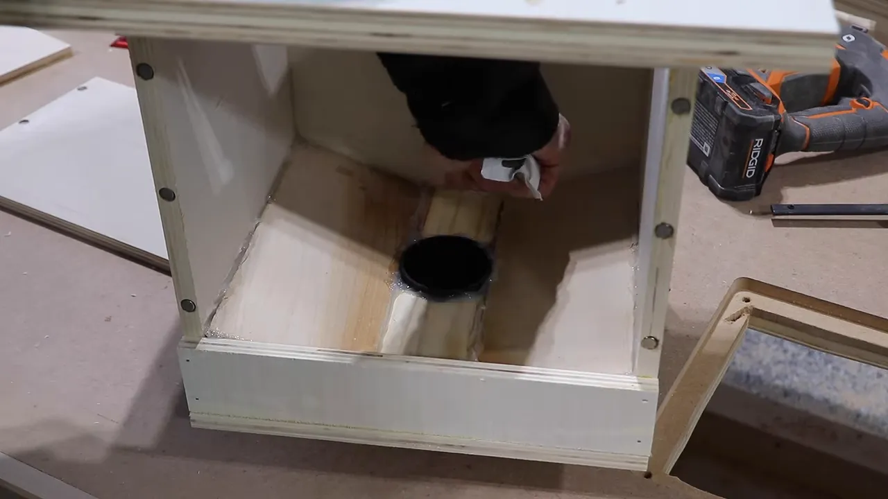
Then, after sealing the box, I needed to put holes in it. Yes, intentionally.
Dust collection needs moving air. If the only inlet is the small opening around the router bit, the enclosure may not get enough airflow to carry debris toward the outlet. The goal is to limit uncontrolled leaks while providing a deliberate path for incoming air.
My approach was to drill a few holes in the removable door, test the collection, and add holes as necessary. An adjustable vent or damper would provide another way to tune that airflow.
Keep the Workbench Electrical System Plug-and-Play
I am not an electrician, and I wanted this system to be approachable without custom wiring. The electrical setup therefore relies on off-the-shelf, cord-connected components.
The arrangement is straightforward:
- A recessed AC inlet accepts an extension cord from the wall.
- The inlet supplies a heavy-duty surge protector inside the bench.
- The internal power distribution serves the bench components and recessed outlets at both ends.
- A dust-collection trigger controls the vacuum system in its cabinet.
The removable incoming cord is useful when moving the bench. There is no permanently attached cord dangling behind it, and an inlet takes up less internal room than a cord reel.
The flush-mount receptacles I selected are rated for 12 amps. That is a component limit, not permission to run any combination of tools through the bench. Check the ratings of the tools, inlet, cords, distribution equipment, and supply circuit.
I specifically planned to plug the table saw directly into a suitable wall outlet rather than through these recessed receptacles. Startup and heavy-cut demands can exceed what those components are intended to handle.
I cut the rectangular outlet openings, circular inlet opening, and dust-port openings while access was still good. Any layout change needs a second check inside the bench. Moving one fitting can easily put it directly in the space needed by a drawer or hose.
Fit Compact Dust Collection Inside the Bench
The built-in collection system has a specific job: serve portable tools around the workbench and provide collection at the router table. It is not a substitute for a high-volume table-saw dust collector.
I paired a small Vacmaster Beast vacuum with a Dust Right separator. The vacuum had a compact footprint, and the separator’s low profile made it practical to fit inside shop furniture.
I had used several of those separators before and liked them. They are not perfect, but they remove a useful amount of solid material before it reaches the vacuum.
The vacuum’s stated airflow was approximately 100 CFM, or cubic feet per minute. For comparison, the separate wall-mounted Dust Right collector I installed for the table saw was rated at 1,250 CFM, using a 1.5-horsepower motor on standard 110-volt power. Those are equipment ratings, not measurements of airflow delivered through the completed hoses.
The distinction matters. A compact vacuum and a larger dust collector are not interchangeable just because both collect sawdust.
Route the hoses before closing up the storage
I used 2-1/2-inch hose and a three-machine fitting kit to connect the system. The blast gates mount through the bench panels, with added mounting holes and the kit’s thumb-screw hose clamps securing the connections.
Some routes are tight. Installing the hoses before securing every insert saves a lot of unnecessary frustration.
The separate, larger table-saw collector made a very noticeable difference, especially combined with over-blade collection. The small internal system remained dedicated to the bench’s own tasks.
Also, a cleaner-looking surface is not a measurement of airborne dust exposure. For supporting safety guidance, OSHA’s wood-dust resources explain why controlling dust at its source matters.
Build the Drawers and Router-Bit Pullouts
Use simple drawers with supported bottoms
The main drawer insert holds four drawers in two sizes. I used the same construction I liked on my shop cabinets because it balances strength and simplicity.
A dado near the bottom of each side captures the drawer bottom. The bottom then screws to the undersides of the front and back pieces. In my experience, this helps support a wide bottom panel when the drawer is loaded with heavy tools.
Four drawers felt pretty manageable after previously building 20 drawers in eight different sizes. Everything is relative.
Turn narrow spaces into accessible bit storage
The router insert includes vertical pullout drawers for router bits. I dedicated one to 1/2-inch-shank bits and the other to 1/4-inch-shank bits, with drilled holders keeping them organized and easy to reach.
You can change that arrangement to fit your collection. The useful idea is making narrow spaces accessible rather than leaving them as awkward little cavities beside the router.
I initially installed the pullouts upside down and corrected them later. Orientation marks are good. Paying attention to the orientation marks is even better.
Seal the MDF and Install the T-Track
Protect the work surface
There are several ways to seal MDF. The important part is actually doing it.
I used three coats of shellac because it dries relatively quickly and produces a hard, protected surface. Light sanding between coats with roughly 320-grit paper helped smooth the finish.
I finished the broad surface before routing the T-track channels, then planned a coat inside the channels to protect the newly exposed material. Routing first and finishing afterward is also a reasonable order.
Test the track fit in scrap
Before routing the actual top, make a test channel in scrap. Check both the width and depth with the exact track you intend to install.
The track should sit slightly below the work surface. I spent most of the test-cut adjustment dialing in that depth.
Prevent exit blowout with a sacrificial backer
My first channel produced some ugly blowout where the bit exited the hardwood edging. A sacrificial backing board would have supported those fibers.
Where conventional clamping was awkward, I used painter’s tape and CA glue to hold a backer in position:
- Apply painter’s tape to the mating areas of the bench edge and backing board.
- Use CA glue between the taped surfaces, with accelerator if available.
- Press the backer firmly into position.
- Route through the edge into the sacrificial board, then remove it.
The result was dramatically cleaner.
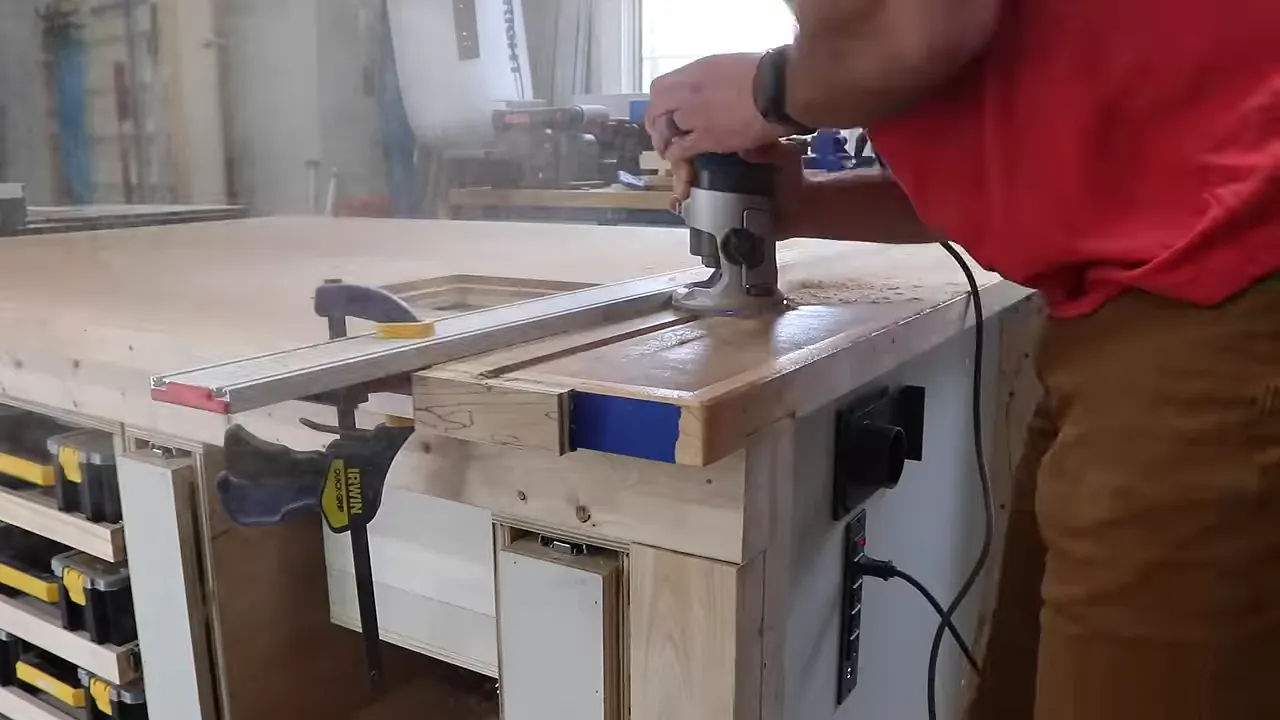
Of course, I then found a screw with the router. Remember the part about marking the track locations before installing trim fasteners? That advice was excellent. My execution needed work.
After checking for additional screws, I finished the remaining channels using straightedge guides, including a longer improvised guide arrangement for the long cuts.
Decide whether to fill the intersections
I installed the track and intended to use intersection fittings where the channels crossed. Temporarily misplacing one fitting highlighted an alternative: leave selected intersections open.
Open intersections can make it easier to insert or remove T-track accessories near the center of a large layout instead of sliding everything in from an outside edge. My track is mostly near the perimeter, so I preferred the completed intersections, but it is a useful design choice to consider.
Add Face Frames, Doors, and Drawer Fronts
I installed the face-frame pieces individually with glue and brad nails. Building the face frame separately before attaching it would give cleaner assembled joints, but individual installation was faster for this project.
A small intentional gap above the face frame accommodates minor discrepancies between it and the main frame. Once assembled, that gap is out of sight.
The doors and drawer fronts are flat panels with a simple chamfer. You can change the door style without changing the basic storage concept.
Use the hardware holes to position drawer fronts
Mounting drawer fronts does not need to be a mystery. This is the method I used:
- Predrill the handle holes in the drawer front.
- Position the front with spacers or careful measurements.
- Temporarily screw through those holes into the drawer box, using suitable pan-head screws to hold the front without damaging the holes.
- Open the drawer and secure the front from inside with its permanent screws.
- Remove the temporary screws.
- Extend the handle holes through the drawer box and install the hardware.
The temporary fasteners act as clamps, and their holes become the hardware holes you needed anyway.
Use adjustable hinges for the doors
I used European-style 1/2-inch-overlay hinges. They require large cup holes in the doors, followed by mounting screws for the hinge hardware.
A hinge jig can simplify the layout, but careful marking works too. A self-centering drill bit is useful for the screw holes. Mine was jammed, so I marked the centers by hand.
A spacer beneath the door established its position while I attached the hinges to the face frame. The adjustment built into these hinges lets you fine-tune the fit afterward.
Prep, Paint, and Reassemble
Once everything fit, I took the necessary parts back off for paint preparation. That meant sanding rough areas, filling nail holes and voids, and cleaning up the details that paint would otherwise make more obvious.
I masked the protected surfaces, turned the area into a temporary paint booth, and sprayed the cabinet components with my handheld Graco sprayer.
After painting and reassembly, the bench finally looked like the thing I had been imagining through all the plywood cutting, glue-ups, and occasional moments of serious life contemplation.
Better yet, it was ready to use. Almost. Naturally, I still needed to finish the router-table upgrades.
Install an Accessible Router Switch
The external router switch was already included in my plan, so there was no good excuse for putting it off.
I mounted the switch body from the inside of the door so the controls were accessible from outside, then added a simple 3D-printed bezel to hide the exposed wood around the opening.
That cleaned up the appearance and, more importantly, gave me a quick way to shut off the router without reaching into the cabinet.
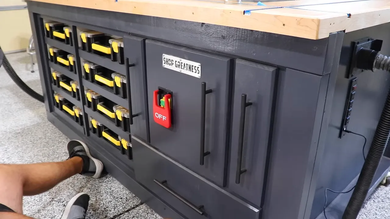
Build a Custom Router-Table Fence
The fence made the biggest difference to the finished router table. I considered buying one, but building it let me match the bench’s T-track arrangement and customize the faces.
The frame starts with a three-foot length of 3-by-3-inch aluminum angle. It needs mounting holes, adjustment slots, and a large center opening for the bit and dust collection.
Buying a compatible fence is a perfectly good option. Machining this aluminum was the part of the project I was most concerned about, and parts of it were uncomfortable even after testing. There is no bonus prize for choosing the sketchiest route.
Lay out the aluminum with high-contrast marks
A simple metal-layout trick worked well here. I colored the marking areas with a blue permanent marker, then used a sharp scribe to expose bright lines in the metal underneath.
Actual layout dye does this job too, but a marker provides useful contrast if that is what you have. Center-punch the hole locations before drilling, then deburr the holes and countersink where required.
Machine the frame cautiously
I cut the aluminum to length at the miter saw and, after some testing, used a conventional straight router bit to machine the slots in shallow passes. I used two temporary fence positions so I could machine the opposite slot edges while maintaining the appropriate feed direction.
For the large center opening, temporary fixture blocks held the angle at 45 degrees for cutting on the bandsaw.
This describes my build, not blanket approval to machine metal with any woodworking setup. Tooling, material compatibility, workholding, feed direction, and eye protection all matter. Follow the equipment manufacturers’ guidance, and choose a purchased fence if you are not comfortable with the operation.
Add stationary and adjustable faces
The fence has a stationary face and two movable faces. Plywood or MDF would work, but I used colored MDF panels because apparently every project needs one more unnecessary level of customization.
The supplier offered small panels in 18-by-18-inch and 24-by-24-inch sizes and several thicknesses. That made it possible to get the look I wanted without buying a full sheet.
I fitted the faces to the aluminum frame, installed the adjustment hardware, and added T-track along the top for accessories such as stop blocks. A rear dust port connects the fence to the bench’s auxiliary collection connection.
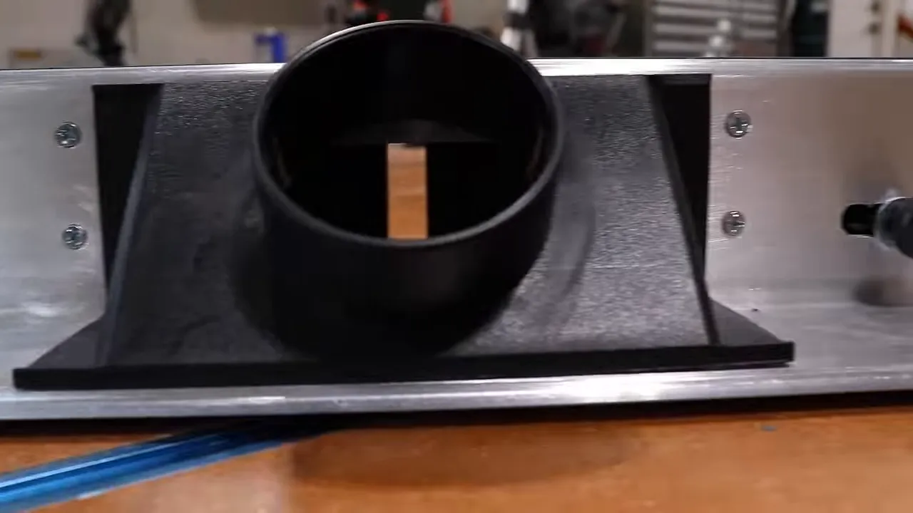
What Actually Made This Workbench Worth Building
The finished bench combines a large work surface with organizer trays, conventional drawers, router-bit pullouts, a router table, accessible power, and hidden dust collection. The individual features are useful, but having them together is what makes the bench work.
The router fence delivered the biggest improvement for two reasons.
First, control and safety. A properly set fence provides a consistent reference surface, and it gives me a place to use accessories such as featherboards rather than relying only on a bit’s bearing when one is present.
Second, dust collection. The system now collects below the router lift and through the fence at the same time. With both paths open, the visible dust reduction during my routing tests was dramatic compared with using the lift without a collecting fence.
I used to assume that getting out a router meant covering the bench, and probably half the shop, in debris. This arrangement changed that expectation.
Was building it worth the struggle? Absolutely. Not because every joint, cut, or installation went perfectly. Clearly, that ship sailed a long time ago. It was worth it because the finished workbench makes the next project easier, cleaner, and more enjoyable.
This project was sponsored by Shopify, the commerce platform I used to build my online plans store. Its customizable storefront and integrations support selling online and expanding a business over time.


